In this research, we developed two phenotyping platforms for in-situ characterization of plant responses to changes in their environment (e.g., management practices, drought, flood, heat, etc.). These platforms consist of two robotic systems: a mobile, observation tower, Vinoculer, for canopy characterization and general inspection of the crop; and a ground vehicle, Vinobot, for individual plant phenotyping.
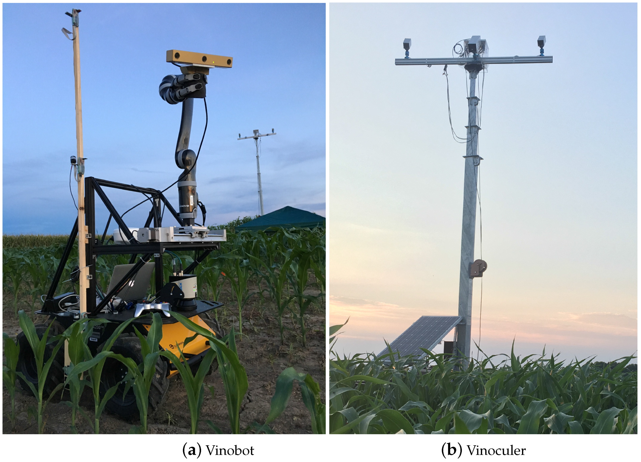
Figure above shows the Vinobot and Vinoculer in a field at the Bradford Research Center near Columbia, Missouri, USA.
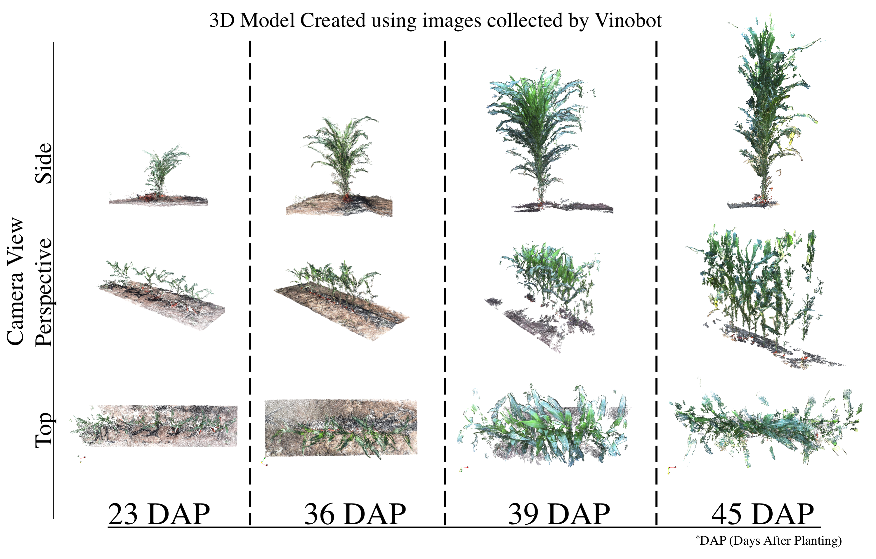
Vinobot (ViGIR-lab Phenotyping Robot) is a mobile platform equipped with a range of sensors designed to fulfill both the phenotyping tasks and its autonomous navigation needs.
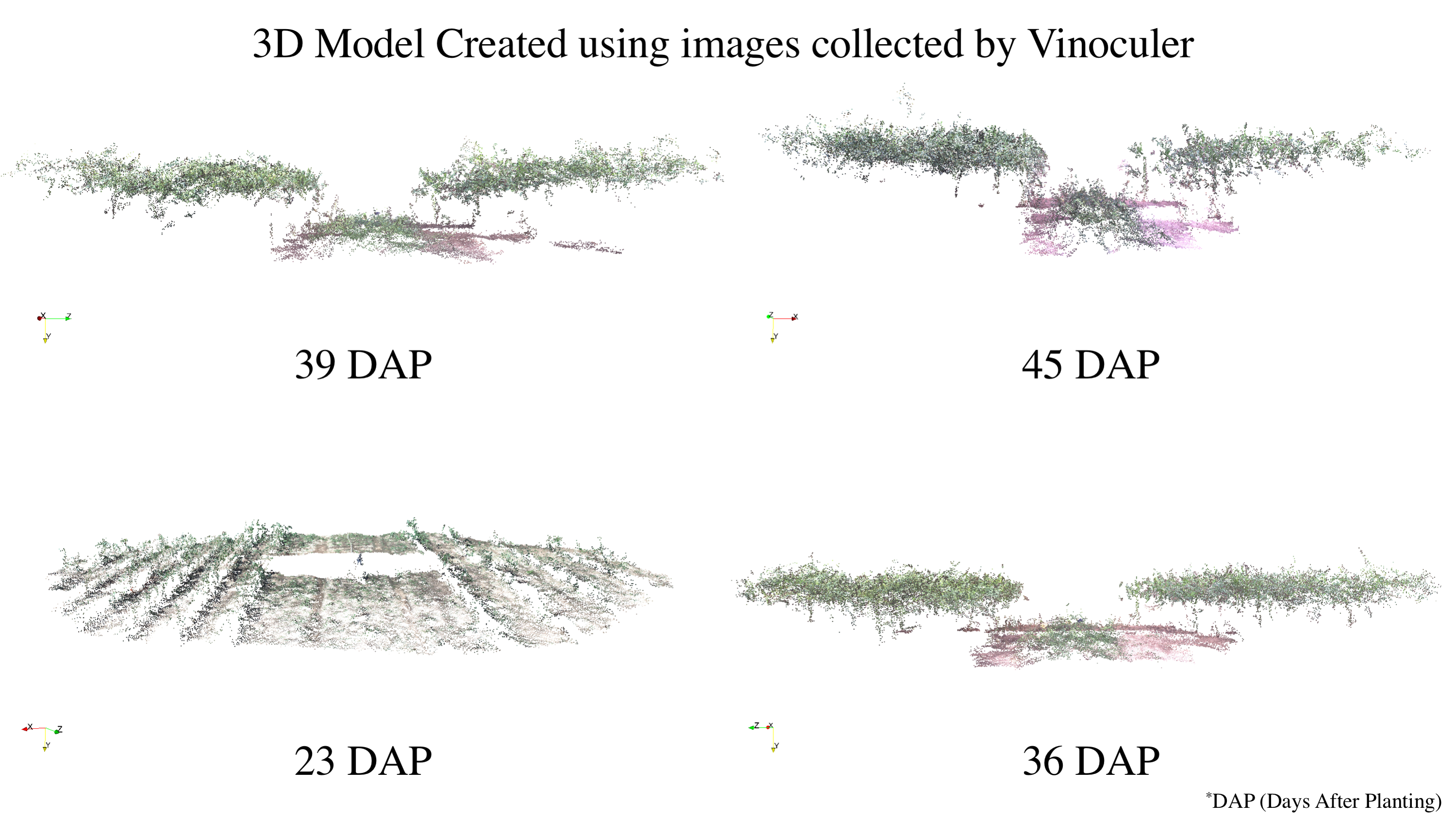
Vinoculer (ViGIR-lab Phenotyping Trinocular Observer) is a mobile observation tower deployed in the center of a field. It is capable of turning 360 degrees while capturing data from a large area. It was equipped with stereo RGB and IR cameras in order to perform measurements such as volume, leaf area, biomass, height, growth rate and other canopy characteristics.
Together, the Vinobot and Vinoculer are capable of collecting data from a large area at the canopy and individual plant level.
I also proposed the use of a trinocular camera rig consisting of a stereo RGB pair plus a thermal camera to create multi-dimensional models of the plants in the field. That is, our system allows both appearance and temperature information to be stored and analyzed for plant phenotyping purposes. We refer to it as a 4D-RGB model, since structural (3D), thermal (+1D) and textural (RGB) information are accurately registered and stored.
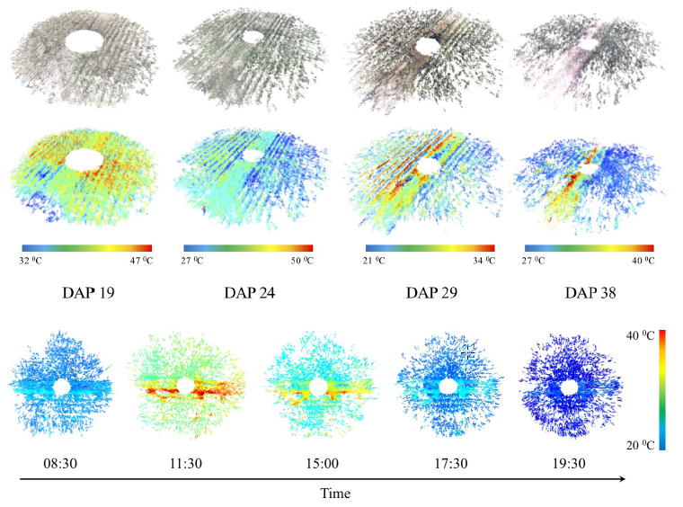
To see the 4D-RGB models click on: 3D-RGB and 3D-Thermal.
Bicycle is an interesting vehicle due to its help in human health and environmental issues as well as being an exciting sport tool for many decades. Balancing a bicycle by a human driver is possible; however, stabilizing an unmanned bicycle is very complicated. The first step in this control synthesis is understanding the bicycle dynamics which is a complex nonlinear system.
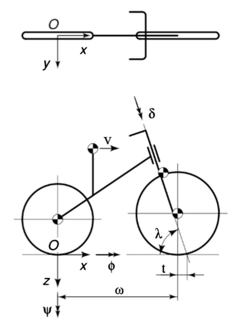
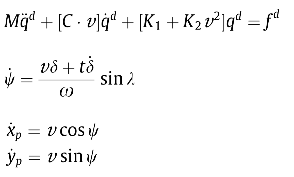
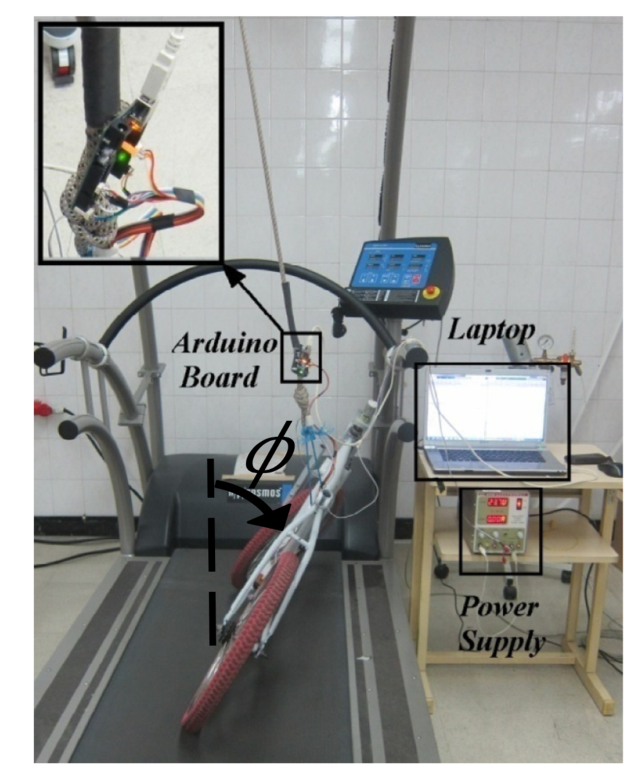
In Figure above, δ shows the steering angle, φ is the roll angle, ω indicates the yaw angle and ν is the forward velocity of bicycle, assumed constant here. The bicycle's equation of motion is:
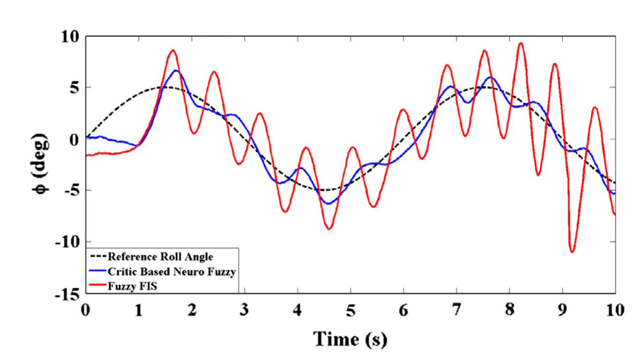
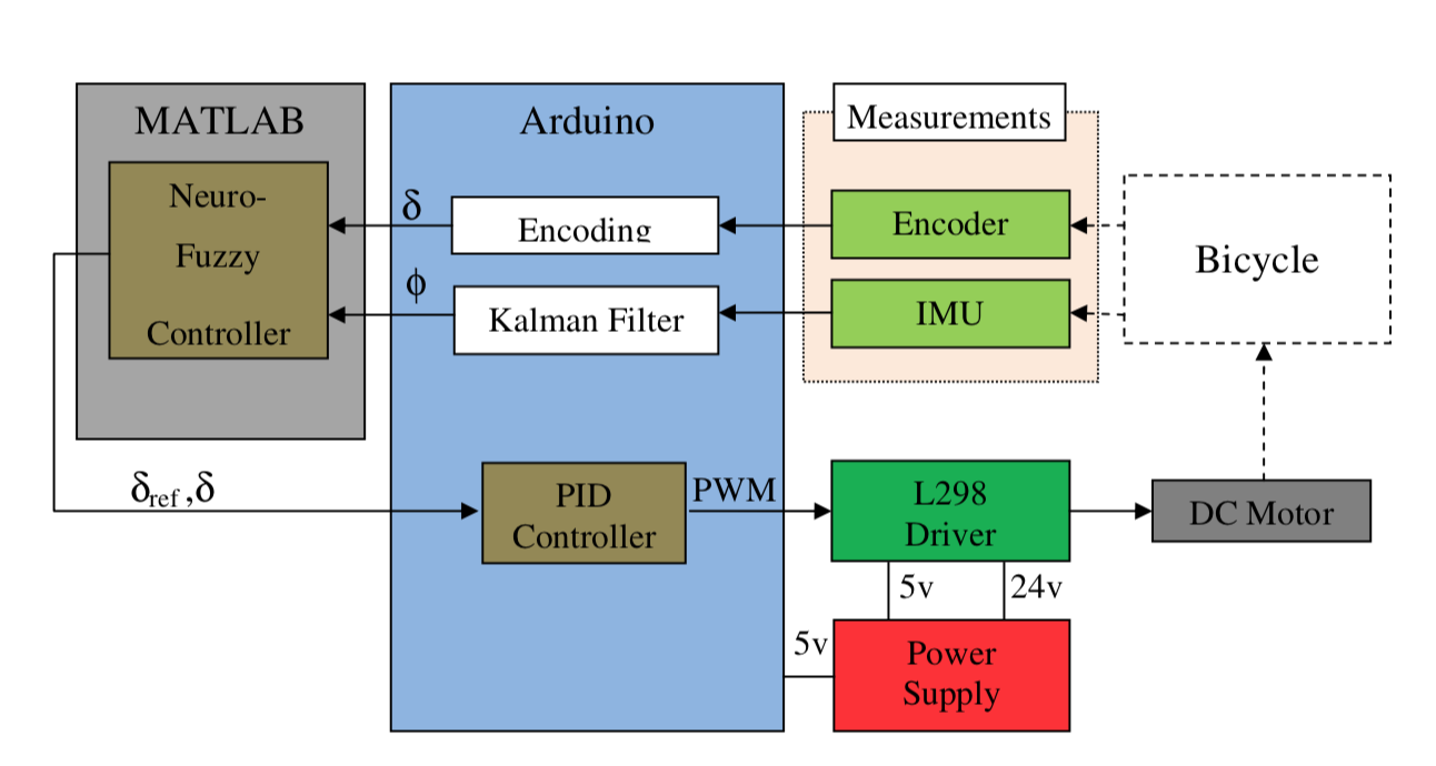
In our work, we designed an adaptive critic-based neuro-fuzzy controller to stabilize the bicycle.
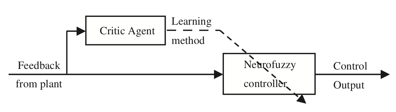
Figure below is the control diagram:
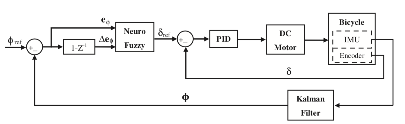
Experiments are designed and conducted here to investigate the capability of our proposed method in practice. The main part of the test setup is a bicycle equipped with an IMU (type MPU6050) which measures the roll angle of bicycle (φ), and a 200 pulse incremental encoder to measure the steering rotation (δ). A micro-controller board (Arduino type UNO) has been used. A geared DC motor produced appropriate torques to turn the bike steering fork. The motor based on our test had 2.5 N m stall torque and reached a no-load speed of 130 rpm at 24v. The motor position control was made by a PID controller whose coefficients were tuned experimentally Kp=40; Ki=0:001 and Kd=1. A tread- mill was used to implement the driving in the lab and run the bicycle with desired velocities according to our test conditions
Results for a sinusoidal roll angle trajectory tracking is shown below: